Reverse Engineering for Foundries
Reverse Engineering for Foundries
Reverse engineering creates data from your master model or from damaged components for which CAD data no longer exists. These CAD data records can be created as STP or as native CAD data with history in various software versions such as Catia, Creo, Inventor or Solidworks. Our TEAM will be happy to help you with 3D scanning and later creating a CAD data set.
Contact Mako GmbH
The reverse engineering service on die casting molds is useful for any customer who wants to expand data on a mold based on the existing product or when molds are damaged. The object is scanned and measured, then converted into a 3D CAD model. By using laser or white light scanners, touch probes and other tactile measurement methods, it is possible to obtain enough information to replicate the shape for die casting aluminum, zamak and brass. If the mold is old and does not contain 3D files or technical data that would allow reproduction, our TEAM offers the reverse engineering service of the die casting mold to obtain a solid 3D CAD model, which provides all the relevant data for the actual making of the mold.
Our reverse engineering process
Our innovative 3-step reverse engineering process focuses on accuracy, efficiency and time saving. Mako GmbH has the internal resources to create high-precision, reverse-engineered 3D models and drawings. The steps we will follow are explained below:
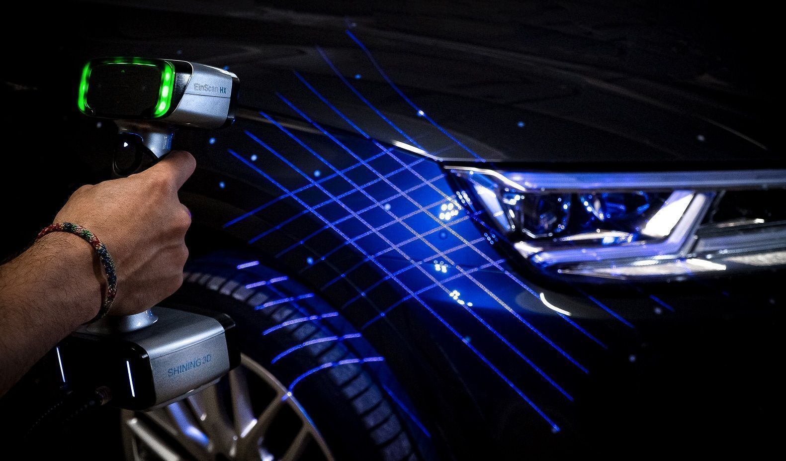
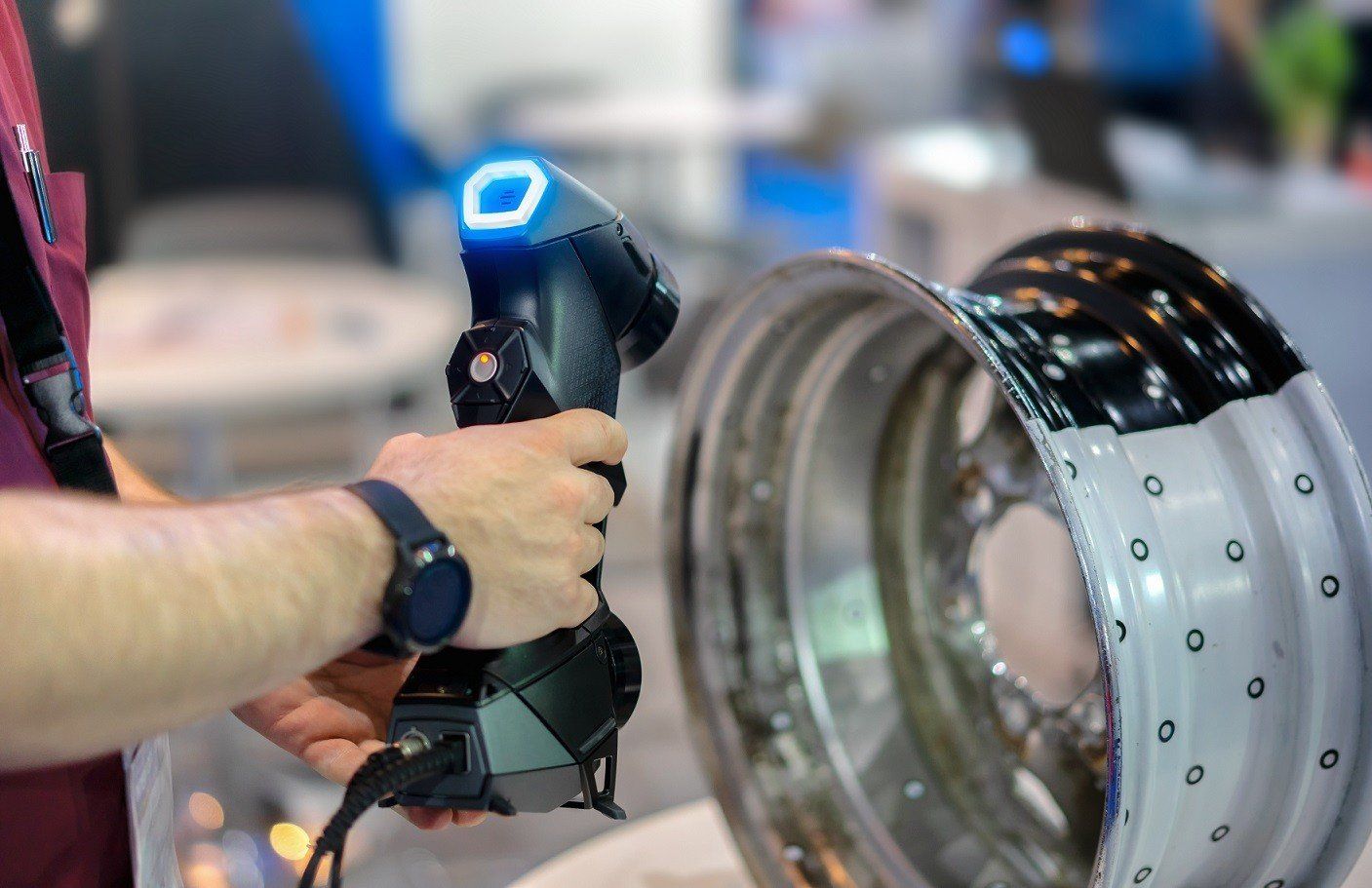
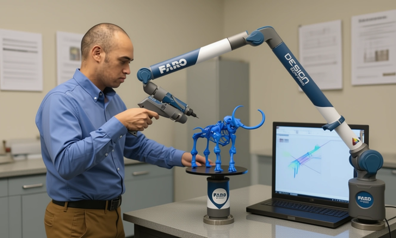
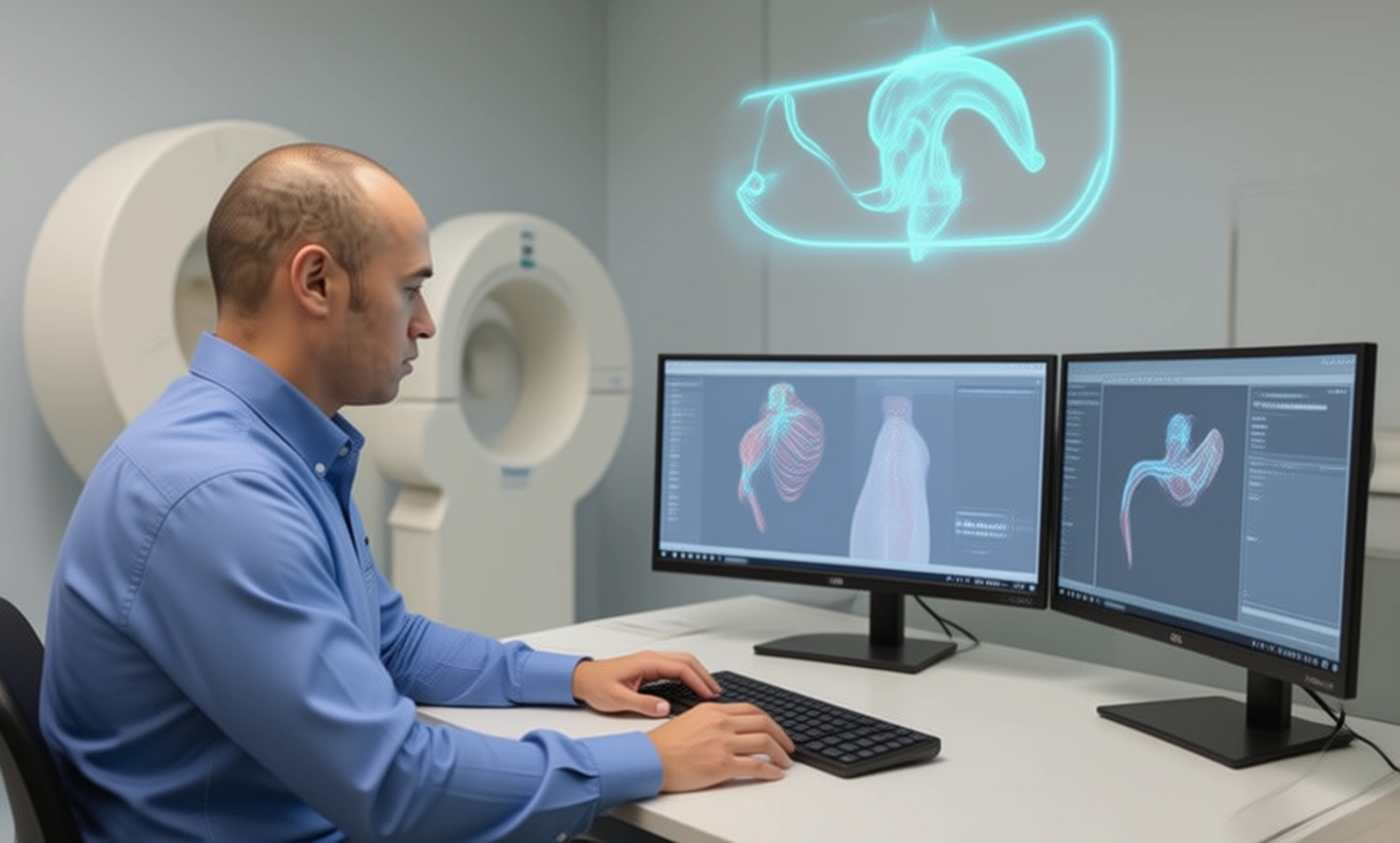
Step 1: SCANNING PHASE
The process begins with the scanning phase. We use the latest 3D scanners such as EinScan HX, EinScan Pro HD, Solutionix C500 etc., depending on the level of scanning accuracy required to scan the tool, to accurately capture all the fine details. The information is collected by scanning with compatible 3D scanning software such as EinScan H from Shining 3D.
If you would like to buy 3D scanners to do the 3D scanning part yourself, we can also help you through our 3D scanner based website. Click here to visit the website and see the high quality scanners we offer.
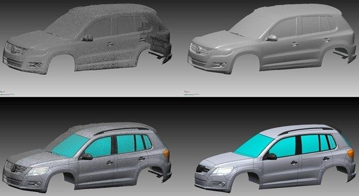
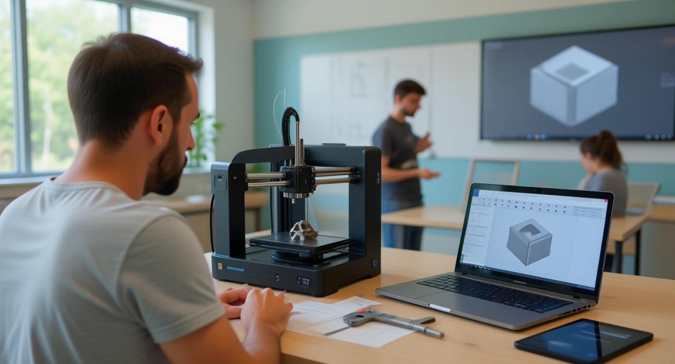
Step 2: MESHING PHASE
In the meshing phase, the digitized raw point cloud model is converted into a polygonal model, a process known as meshing. The raw network data is cleaned and repaired using the tools included in the software package. The compatible EinScan software program can also create new features or make changes as required.
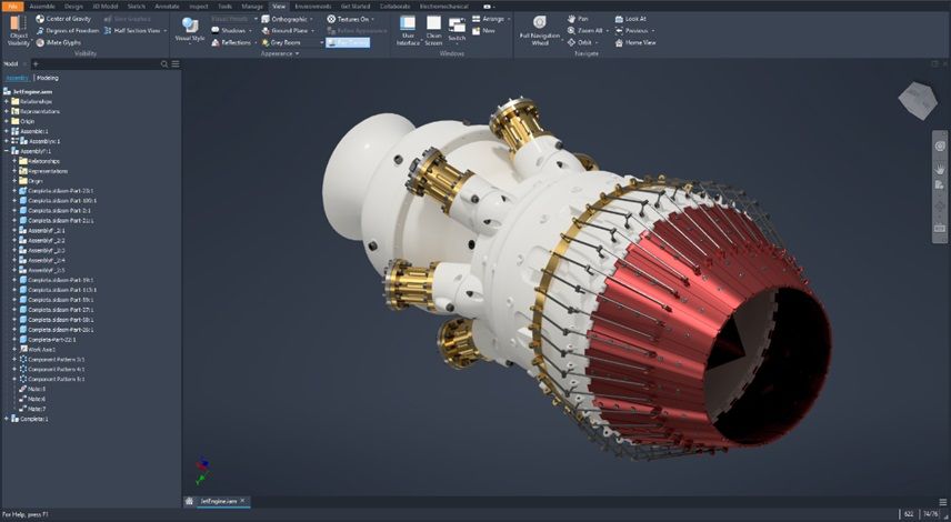
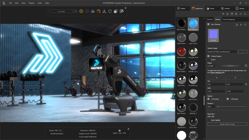
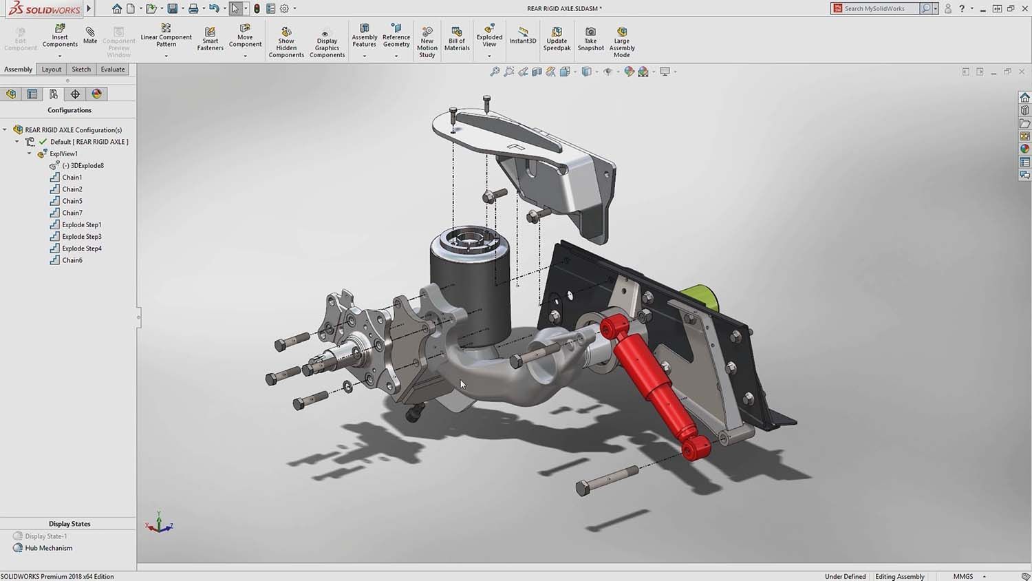
Step 3: MODEL PHASE
In the third and final model phase, a fully functional parametric volume model is created with the CAD software Creo Parametric, Catia, Autodesk, Inventor, Siemens NX or SolidWorks. This process creates a fully editable function-based model if left in its native format or can be exported as a surface model for use in any CAE, CAD, and CAM software.
Mako GmbH uses this three-phase reverse engineering process to support customers in the rapid construction, repair and creation of series models. Cutting edge technology such as the EinScan H software package and CAD software such as Autodesk, Catia, Creo, SolidWorks, etc. help us to lead the way in reverse engineering technology services.
If you have a tool program that is at the end of its useful life and needs to be moved, repaired or replaced, contact Mako GmbH today!
If you’d like to learn more about reverse engineering, CAD software and how to master it, check out our blog posts here or contact us here to get in touch with a reverse engineering expert!
There are no comments