How to Scan an Object for 3D Printing: The Reverse Engineering Workflow
How to Scan an Object for 3D Printing: The Reverse Engineering Workflow
In this Blog article, Reverse Engineering Service expert Mako GmbH describes how to scan objects for 3D printing as part of the reverse engineering workflow.
Reverse engineering is essential when you want to create new parts that reference or incorporate older designs, where the original CAD design isn’t accessible.
For example, you can create replacement parts that match the original design of damaged existing pieces, or use reverse engineering processes to integrate complex surfaces from existing objects into 3D printable jigs, which are useful when modifying mass manufactured and handcrafted products.
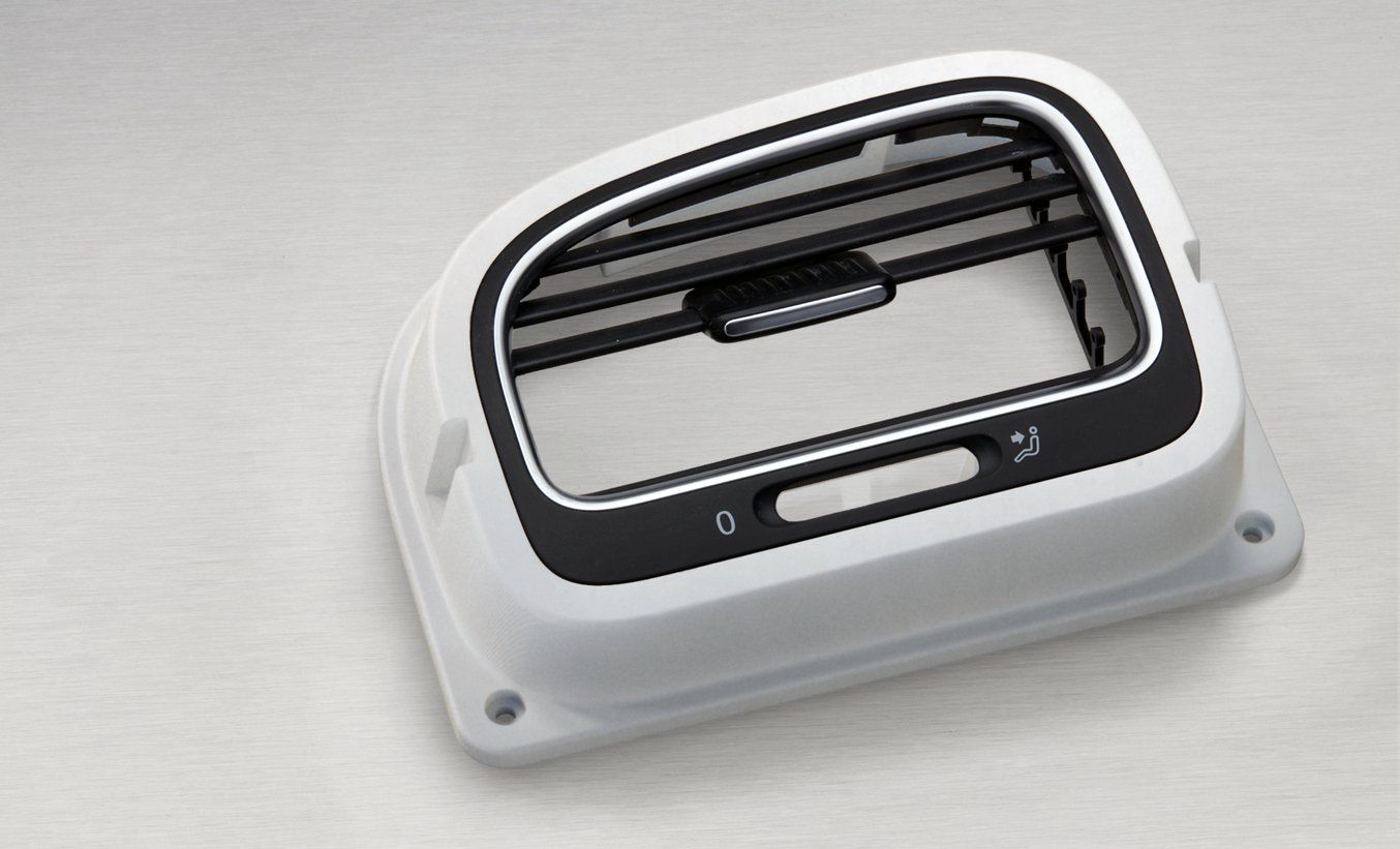
To demonstrate the basic steps in a reverse engineering workflow, let’s take a look at the process for creating an assembly jig for an aftermarket digital gauge that fits onto the air vent of a Volkswagen Golf.
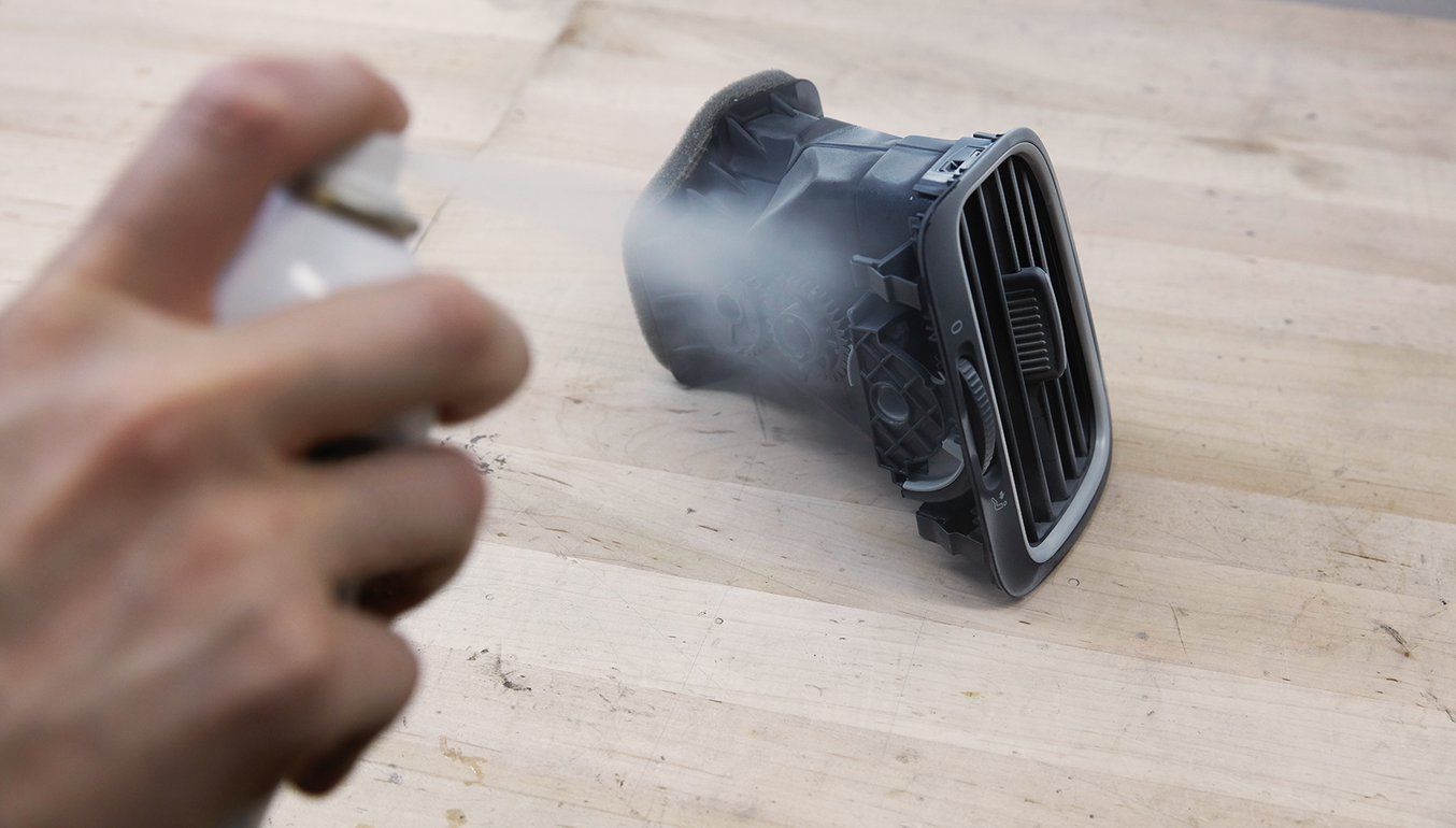
Prepare the Object for Scanning
Spray coat the object with a temporary matte powder to improve scan accuracy. Even slightly glossy surfaces tend to degrade scan quality, while reflective and transparent surfaces cannot be scanned at all without a matte coating.
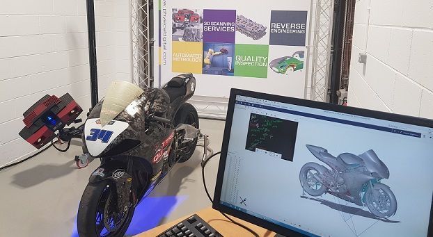
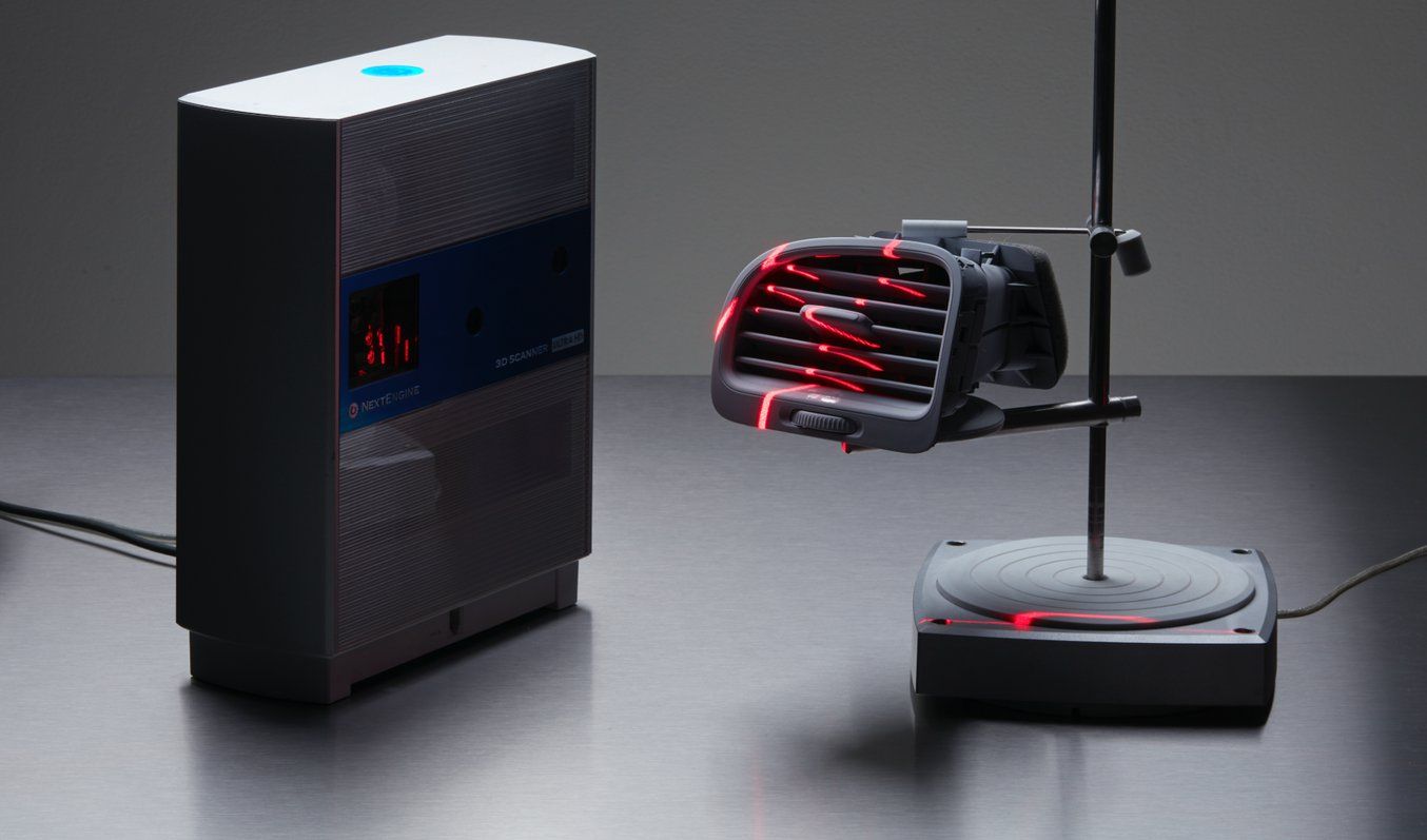
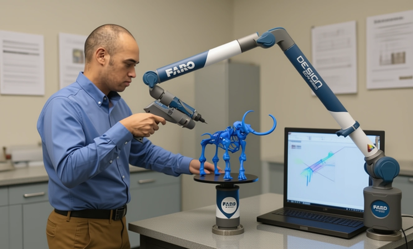
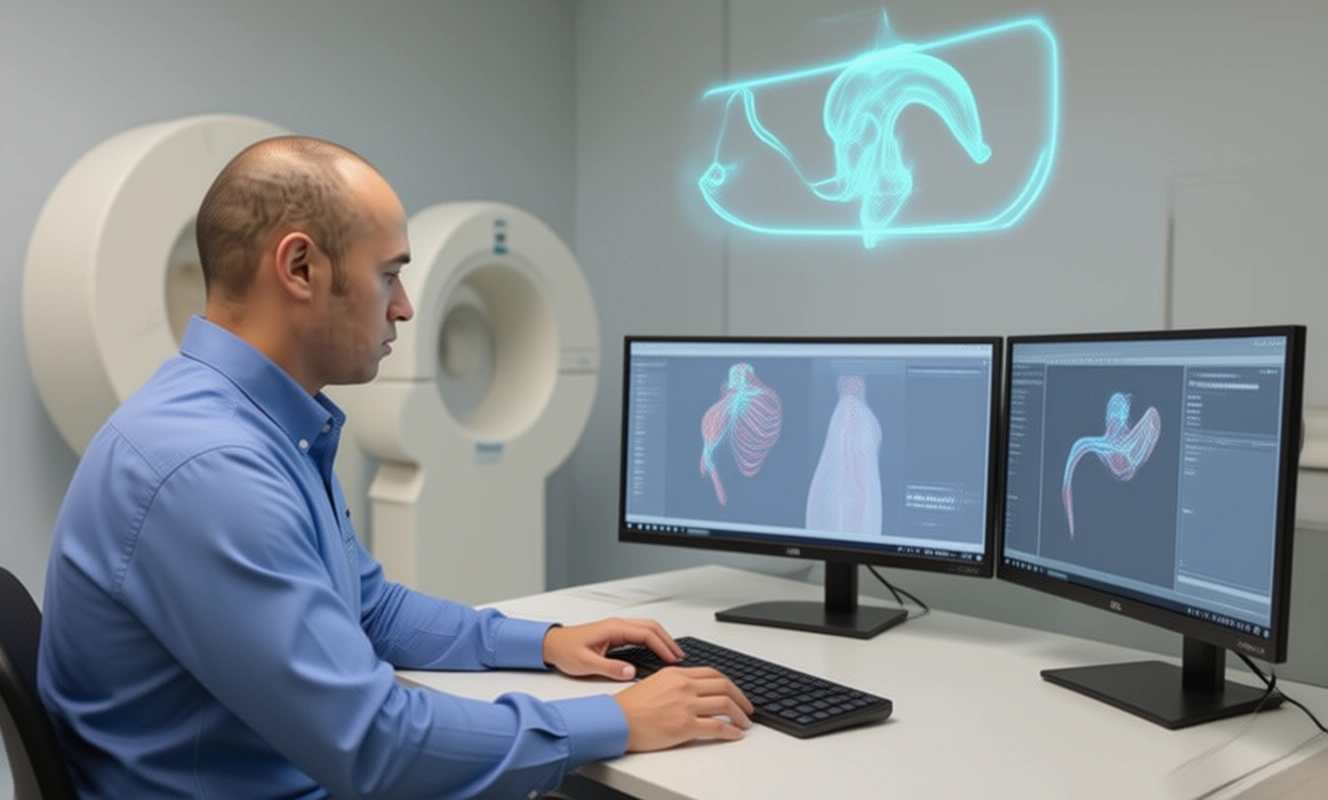
3D Scan the Object
Use a high accuracy 3D scanner to capture the important sections of the part. Tabletop structure light or laser scanners are the right tools for the job, with accuracy of ±100 or better. Learn more about how to choose the right 3D scanner for your application in our 3D scanning white paper.
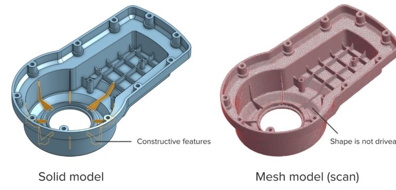
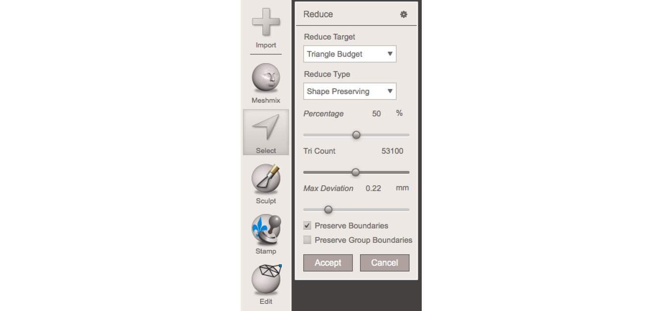
Refine the Mesh
Some scanners produce extremely large mesh files, which will make later steps grind to a halt. Scanner software repairs small gaps and simplifies the scan, making the data more manageable in CAD. Try to reduce the model as much as possible without destroying important details.
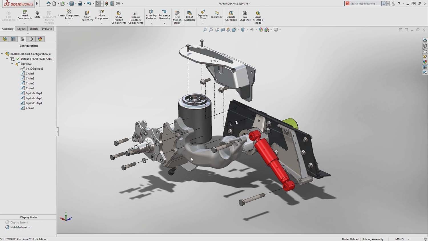
Import the Mesh to CAD
Import the mesh into CAD software equipped with reverse engineering tools. We use Solidworks, which is a powerful choice for resurfacing complex, organic shapes.
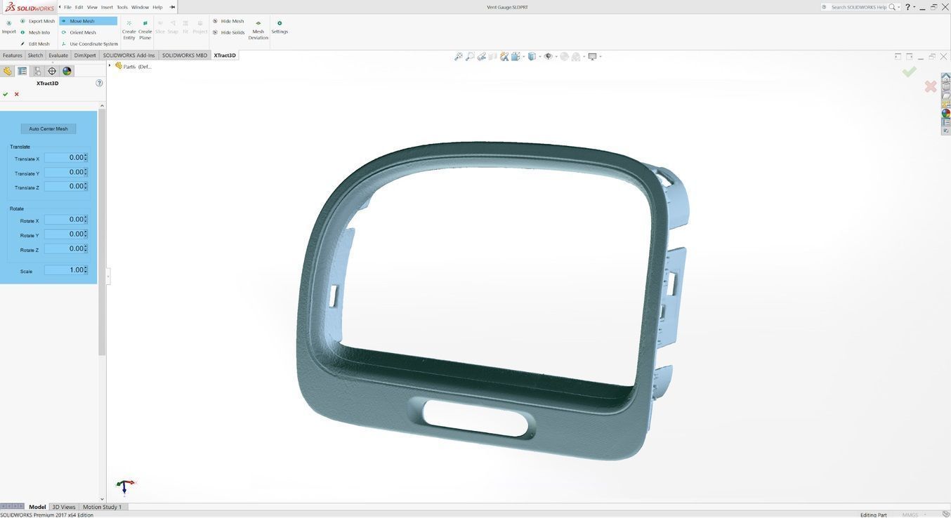
In this step, move and rotate the scan mesh into alignment with any existing design components.
Extract Important Surfaces
There are three paths to extract the shape of the scan in order to create a solid model that is editable with CAD tools: semi-automatic surfacing, automatic surfacing, and manual redrawing.
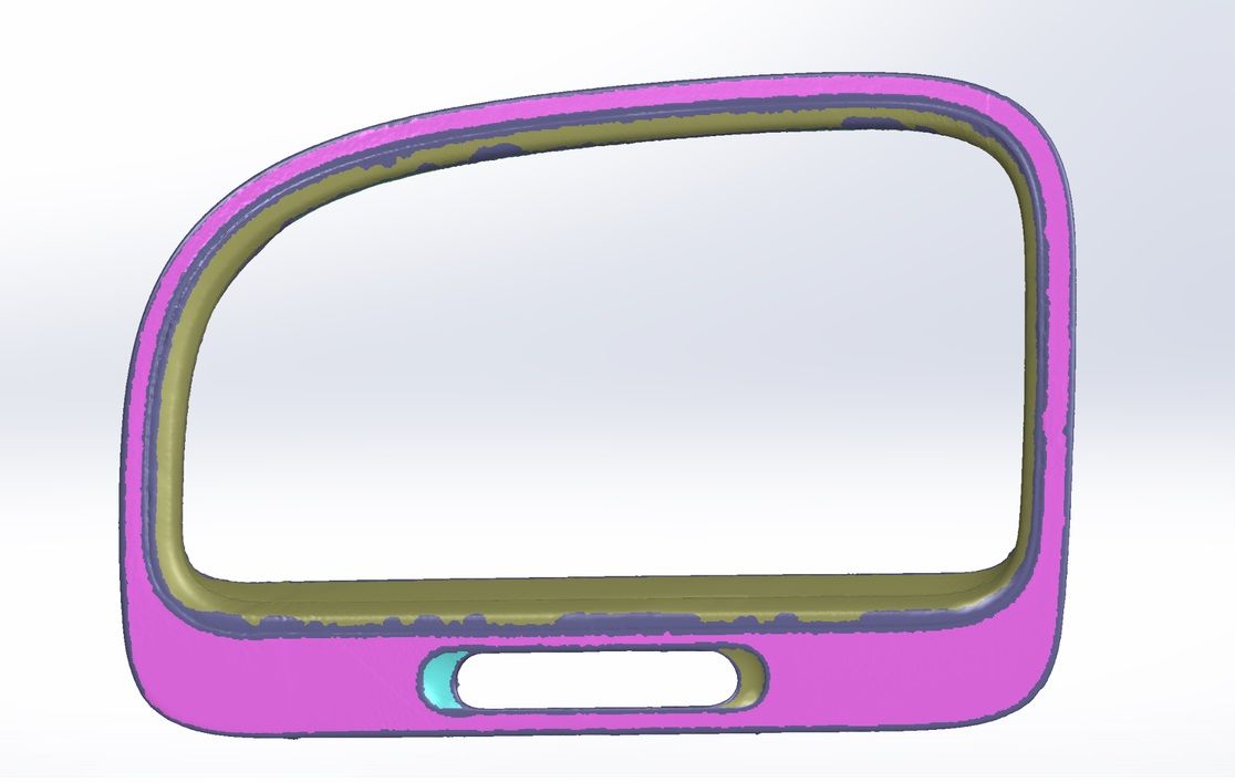
Semi-automatic surfacing
Complex curved surfaces are difficult to manually draw, so you may choose to use semi-automatic surfacing. This function generates surfaces that fit to detected regions of the scan. By varying the sensitivity of the surface detection function, different surfaces will be found.
Automatic surfacing
Automatic surfacing generates a solid model from any watertight scan. You can use standard CAD tools to subtract and add to this auto-surfaced body, but it will be more difficult to move basic features around on the body itself. You may not need control over edge placement. For example, if you are scanning a part of the human body to create custom ergonomically-shaped products, or want to create a jig to precisely or repeatedly modify a handmade object. In these cases, automatic surfacing is a great way to save modeling time.
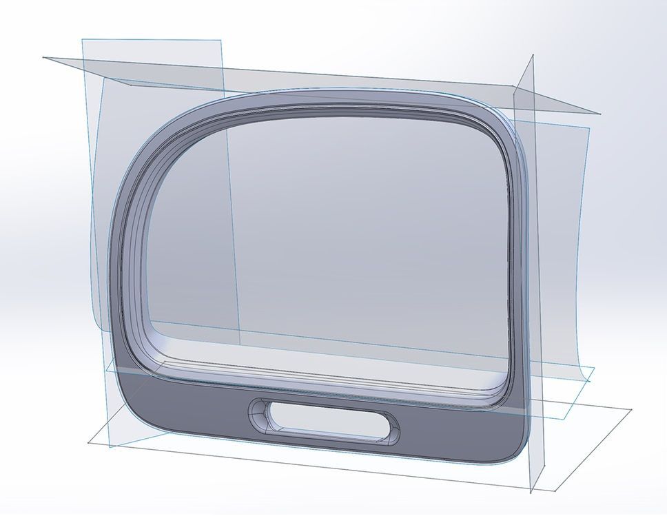
Manual redrawing
For simple features such as bosses, holes, and pockets, it’s usually fastest and most accurate to redraw the features using the scan model as a reference. Reverse engineering software allows you to create sketch planes aligned with flat surfaces on the scan and to extract cross sections from the scan mesh, which helps you match the shape of the original object.
Integrate New Objects
Once the scan has been converted to a solid, it can be subtracted from another solid body to create a jig that securely holds the original part.
The design of the new gauge component also references the dimensions of the scan, using curves extracted with semi-automatic surfacing.
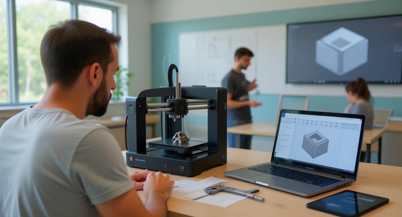
3D Print the New Design
Printing the jig on a 3D printer gives you a high degree of accuracy comparable to the output of engineering-grade 3D scanners.
If you want to explore more about Reverse Engineering, CAD software and how to master them check out our Blog Posts here or contact us here to get in touch with a Reverse Engineering expert!

There are no comments