Reverse Engineering for Constructions

Reverse Engineering for Constructions
During the reverse engineering process, we need to generate the CAD file in the software most suitable for the particular project. During this process, we work regularly within the program. Here we save the construction history of all the steps we have taken. You can then access this history as part of the data we provide. Would you like to use reverse engineering for constructions? Mako-Technics will be happy to show you how to use it. In this post we have summarized the most important guidelines of the process for you. We explain the process from the construction steps to the final output. If your RE process is to be successful and error-free, we must strictly adhere to the following instructions.
Reverse engineering for constructions: parametric functions
While we are doing the RE manually, we can generate parametric functions at any point. We do this wherever it is useful. These functions can be used in any CAD software for parts with regular geometry. Parametric functions are very useful in many places when working with CAD files.
We generally work with the following data sources:
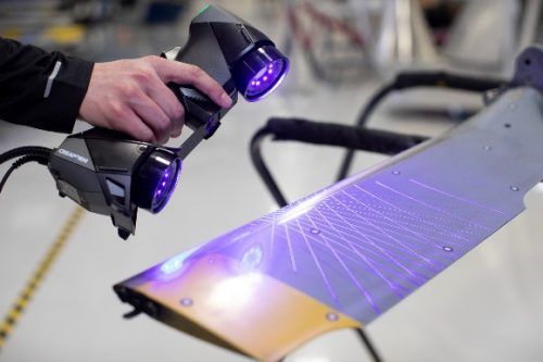
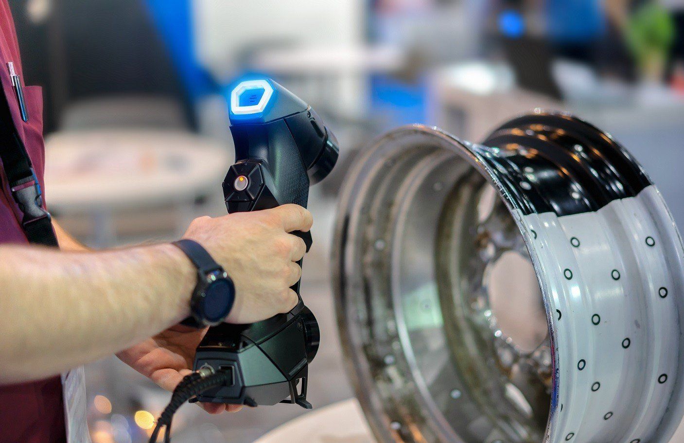
- 3D scans (e.g. clay models),
- Simulations (FEM, ANSYS or material flow in molds – Cadmould or Moldflow) and
- Optimizations (optimization of the product tolerance – GOM Inspect Pro).
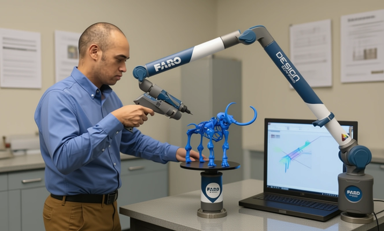
Reverse engineering of 3D scans
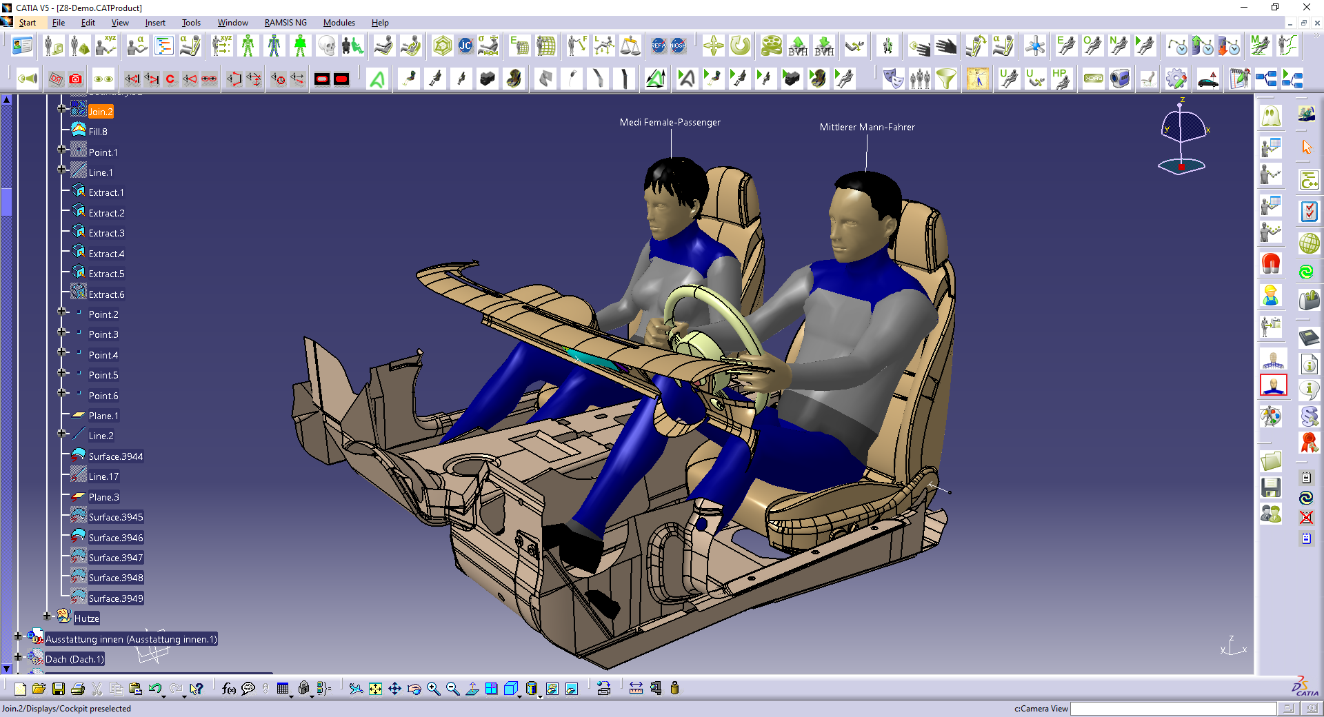
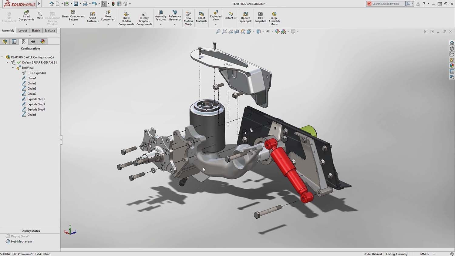
If we work with 3D scan data, we have created the process for you here with which we convert it into parametric CAD data. We follow the steps listed here in order:
- Rough sketch on paper.
- We create detailed units of the model.
- Then we change the units until they fit into the point cloud.
- Now let’s add parametric functions to the units.
- We continue to convert the units.
- Then we add more parametric functions.
- Now we compare the data from Pointcloud and CAD regularly. This is how we ensure that they fit.
- We assemble the parts.
- Finally we check again whether the tolerances between the STL and CAD data are below the requested values.
If small tolerances are to be achieved, our engineers change the structure into smaller elements. You then return to step 5 of this list. We repeat the whole thing until the RE reaches the required tolerance. Reverse engineering for constructions. The areas of application are almost unlimited. You too can use the services of RES.
Reverse Engineering of simulation data
Pointclouds in this case, are a result of simulations done with original straight and clean CAD data. Each simulation affects the structure of the original file. As a result, we would need to rebuild many free forms faces and implement the models into the original CAD software.
The general steps followed when creating native CAD data from Pointclouds based on simulation data include:
- Check original CAD and pointcloud after simulation
- Identify geometrical parts and free form faces
- Rebuild first geometrical units of the model
- Modify the units until they fit on the pointcloud
- Rebuild free form areas and implement them into the geometrical base
- Continue remodeling the units further
- Compare pointcloud and CAD data regularly to ensure allowable tolerances
- Assemble all the parts together.
- Ensure requested tolerance between simulation file and CAD data are below requested figures
If tolerances can‘t be reached on the first attempt, the engineer will modify the structure into smaller elements and progress from step 5 of the above list, until the target tolerance is reached.
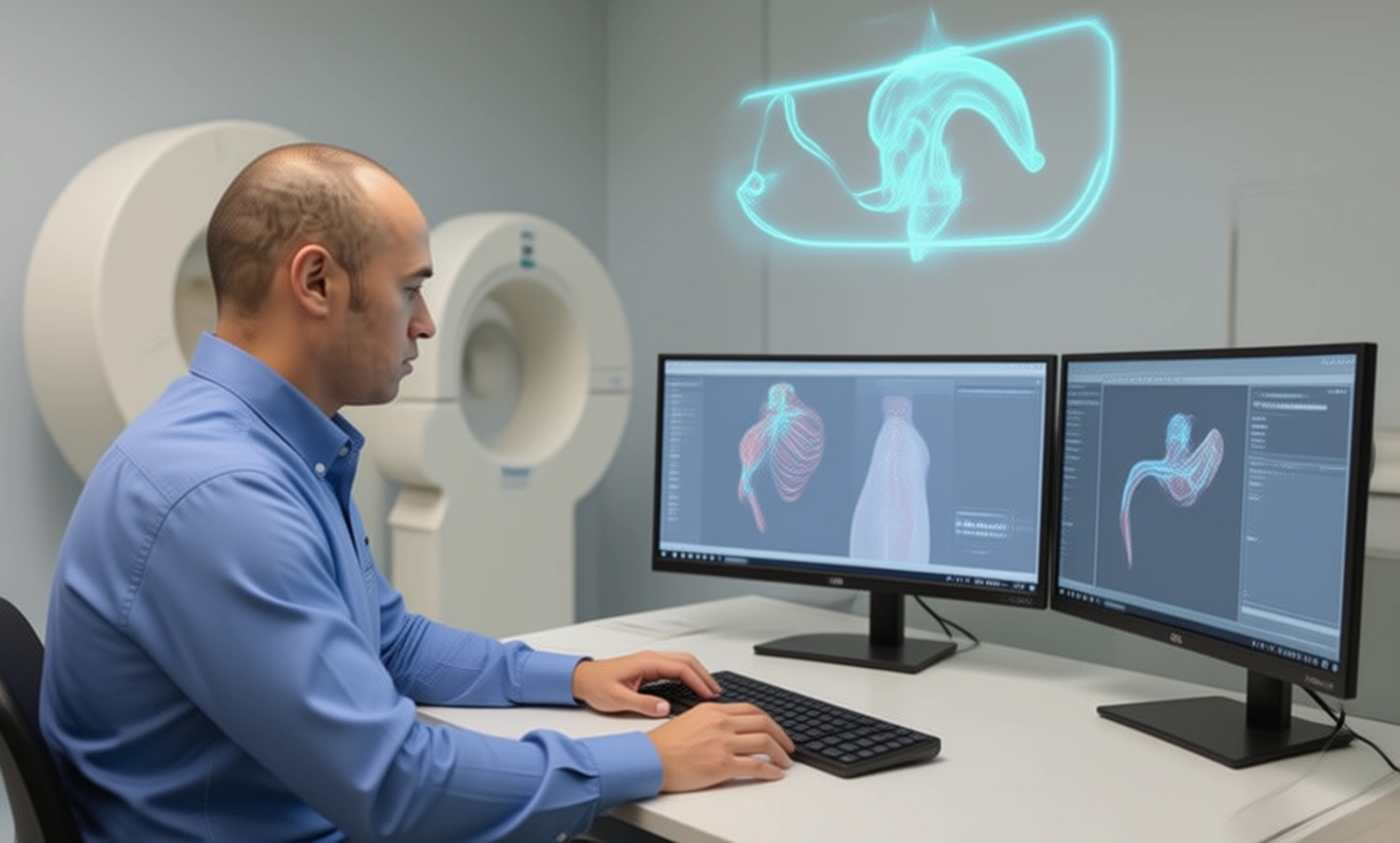
Reverse Engineering of pointcloud
Large objects can be complicated to scan and duplicate.
When reading the surface of a large object, the error margin can be huge and, the scanner might pick damage or dirt that’s on the surface.
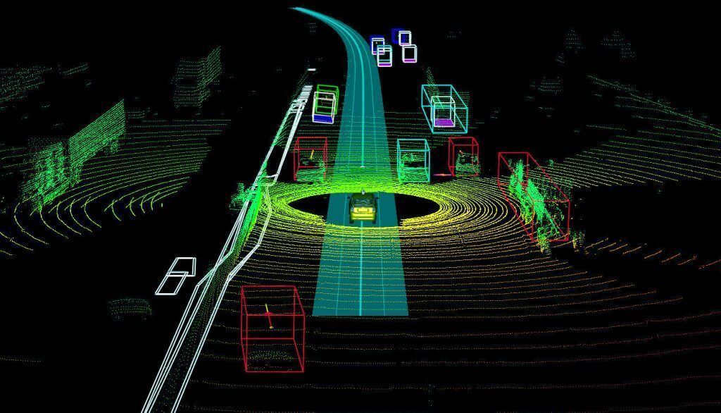
Hence point clouds. Pointclouds are coordinates in space that represent a scanned object. After scanning, the points are then put together to create CAD data.
Below is the process we should follow when reverse engineering generated Pointclouds:
- Checking original CAD and pointcloud after 3D scan
- Generate average pointcloud file out of 5 test parts
- Rebuild geometrical units of the model
- Modify the units until they fit on the pointcloud
- Remodel free form areas and fix them into the geometrical base
- Continue with further units
- Compare data base and cad model regularly to ensure tolerances are reached
- Assemble all faces together.
- Ensure tolerance between simulation file and CAD data are below the tolerance that the customer is asking for.
It is standard practice to cut the CAD structure when dealing with large file sizes. The different parts are then combined to form the original geometry.
There are no comments