Reverse engineering: Tool Correction
Reverse engineering: Tool Correction
In the course of their production, tools bring about some improvements and corrections. Reverse engineering can actively contribute to significantly reducing such work steps. For you as a company, this means, on the one hand, cost savings. On the other hand, getting to market earlier also gives you a competitive advantage.
Are you interested in reverse engineering in tool offset? Then you are exactly right here. In this article, the reverse engineering service team gives an insight into the process and advantages.
Do you need help quickly from reverse engineering experts? Contact the engineers at Mako GmbH directly here.
Why does Reverse Engineering make tool offset more effective?
When plastics get cold, so-called volume contractions usually occur due to shrinkage and shrinkage. These must be taken into account in the production of injection molds for tool production. This is the only way to maintain tolerances during development. In the course of its manufacture, a tool therefore goes through several phases of correction. On the one hand, they are very time-consuming. On the other hand, with high costs.
Reverse engineering enables engineers and designers to be more effective at this tool correction. The reason for this is the omission of some work steps. For example, there is no need to specify starting points for the later CMM measurement of your first components. Furthermore, the manual comparison of the recorded data with the respective target data of the CAD model is no longer necessary. Reverse engineering eliminates these steps.

How does Mako GmbH help with tool correction?
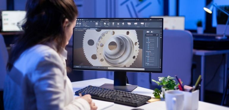
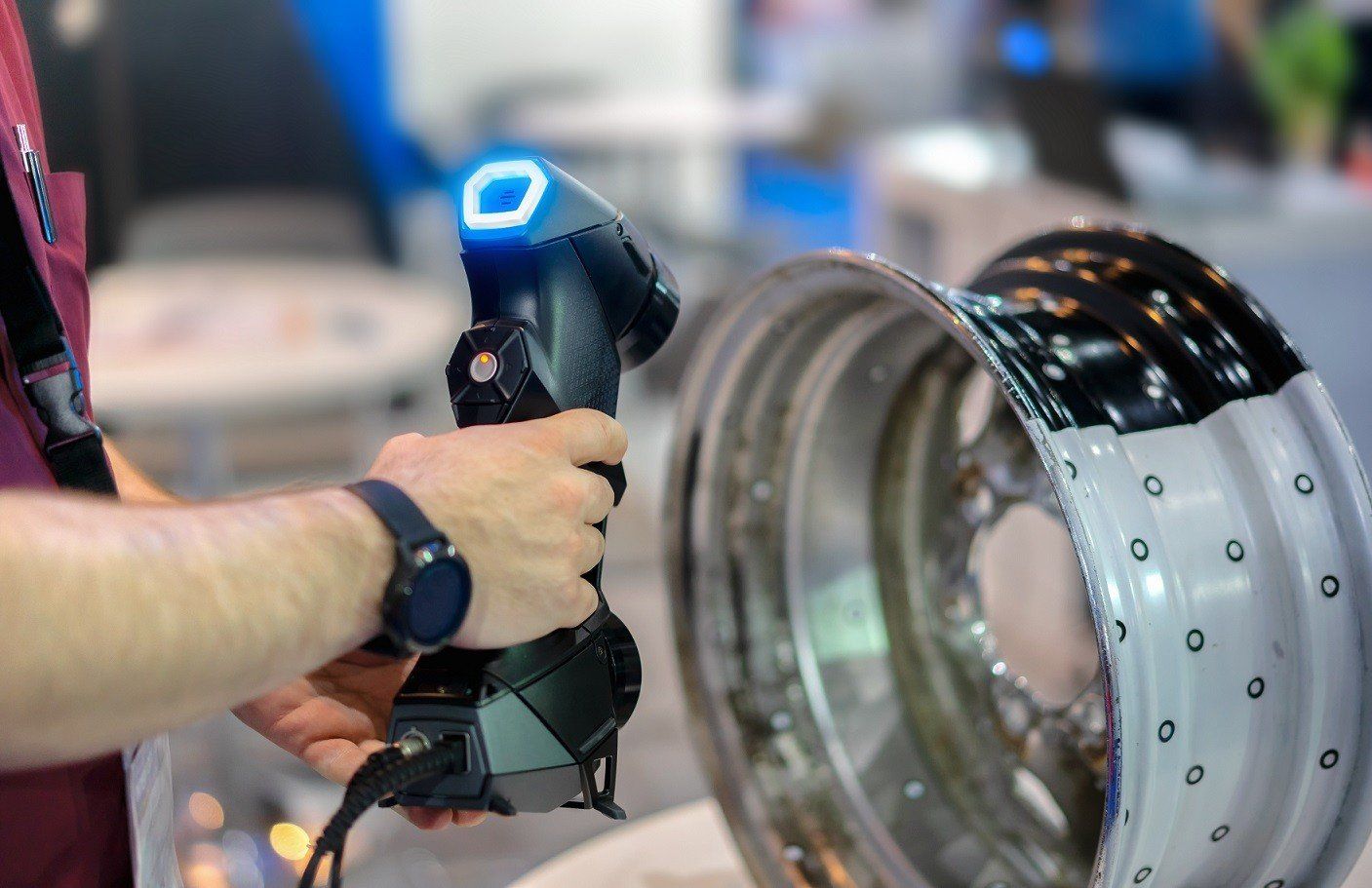
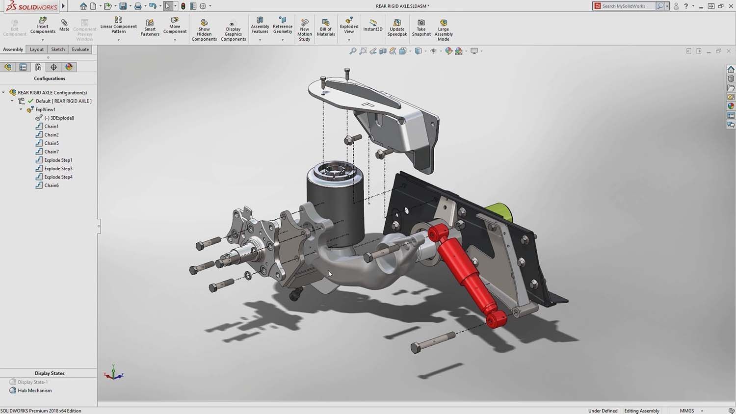
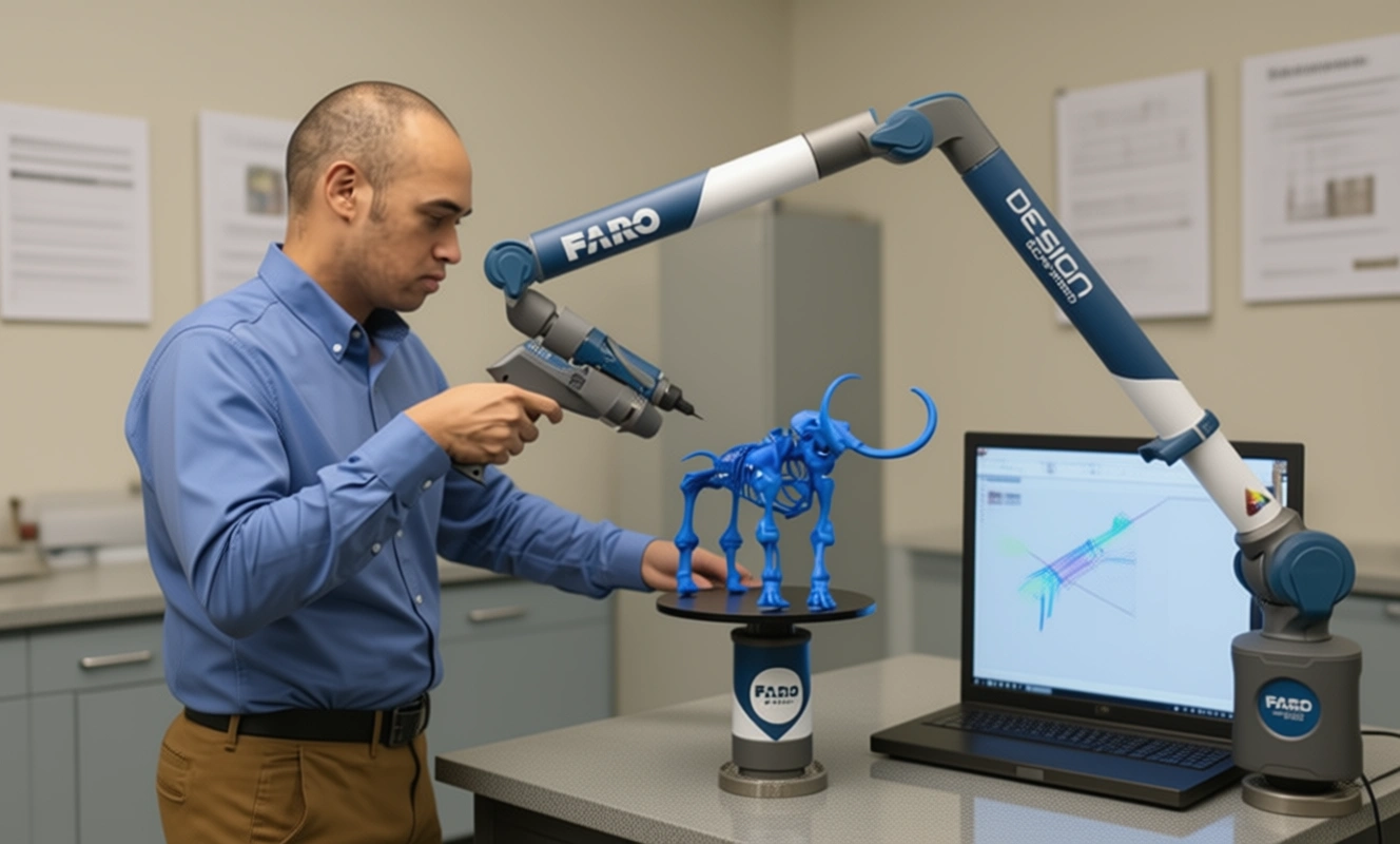
The experts at Mako GmbH, based in Germany, are specialists in the field of reverse engineering. We’ll start by scanning your first components. We use 3D scanners for this in most cases. We then compare the data generated in this way for shrinkage, deviations and delay. We are now able to optimize the point cloud that has been created. We use reverse engineering to convert this from a polygon mesh to a CAD volume model. So we’re converting an STL file to a STEP file.
We then perfect this CAD volume model based on the tolerances agreed with you. The data obtained in this way then serve as the basis for your tool correction.
Would you like to find out more about this? No problem. Contact us today! We are looking forward to your message.
If you would like to find out more about us or reverse engineering, take a look at our blog. There we offer you informative added value with regularly new topics.


There are no comments