Reverse Engineering for Repairing Parts
Reverse Engineering for Repairing Parts
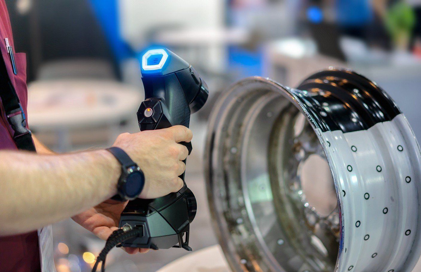
In this article, Reverse Engineering Service expert Mako GmbH tells how industry specialists use Reverse Engineering in repairing of various tools, equipment and spare parts. Reverse engineering has gradually evolved into a powerful tool in the electronic repair process.
What are the Problems you face?
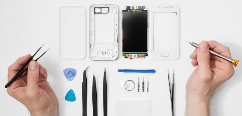
Damaged or broken parts are generally too expensive to replace, or are no longer available. The repair and maintenance of equipment, including simple products to complex items like surgical instruments and diagnostic devices, can be compared to the maintenance of a motor vehicle, something many of us understand well.

If you had a car, would you drive it until the fuel runs out or until a tyre punctures, and then abandon it to buy a new car? Of course not. You need regular maintenance and repair of your products, assets and equipment. This is where reverse engineering comes in.
How Reverse Engineering helps in Repairing?
RE can be defined as: ‘Systematic evaluation of a product with the purpose of replication. This involves design of a new part, copy of an existing part, recovery of a damaged or broken part, improvement of model precision and inspection of a numerical model. Advantages of the technique include immediate feedback, data reduction and direct generation of geometry and higher precision of the final product. This process shows some possibilities of use and benefit from utilising the RE-methodologies and techniques in production process, especially in the case when exists parts without 3D-CAD support.
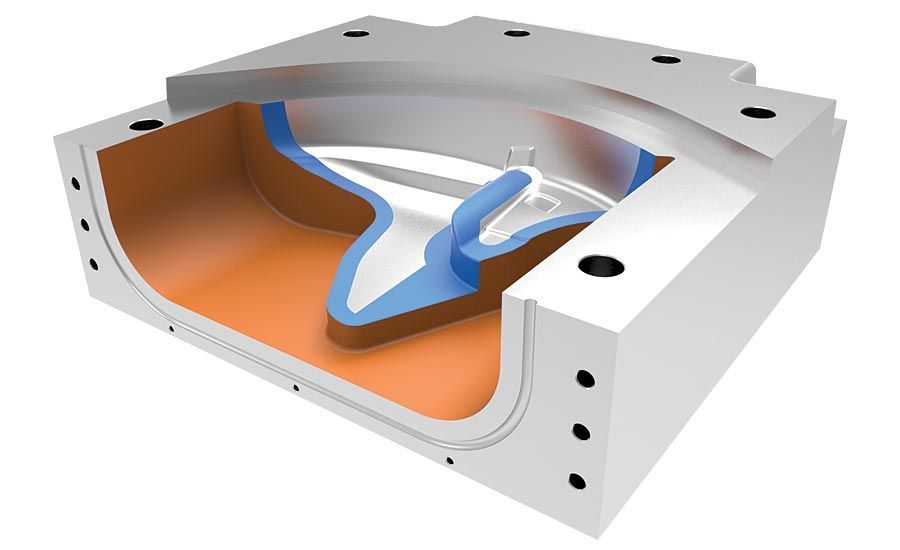
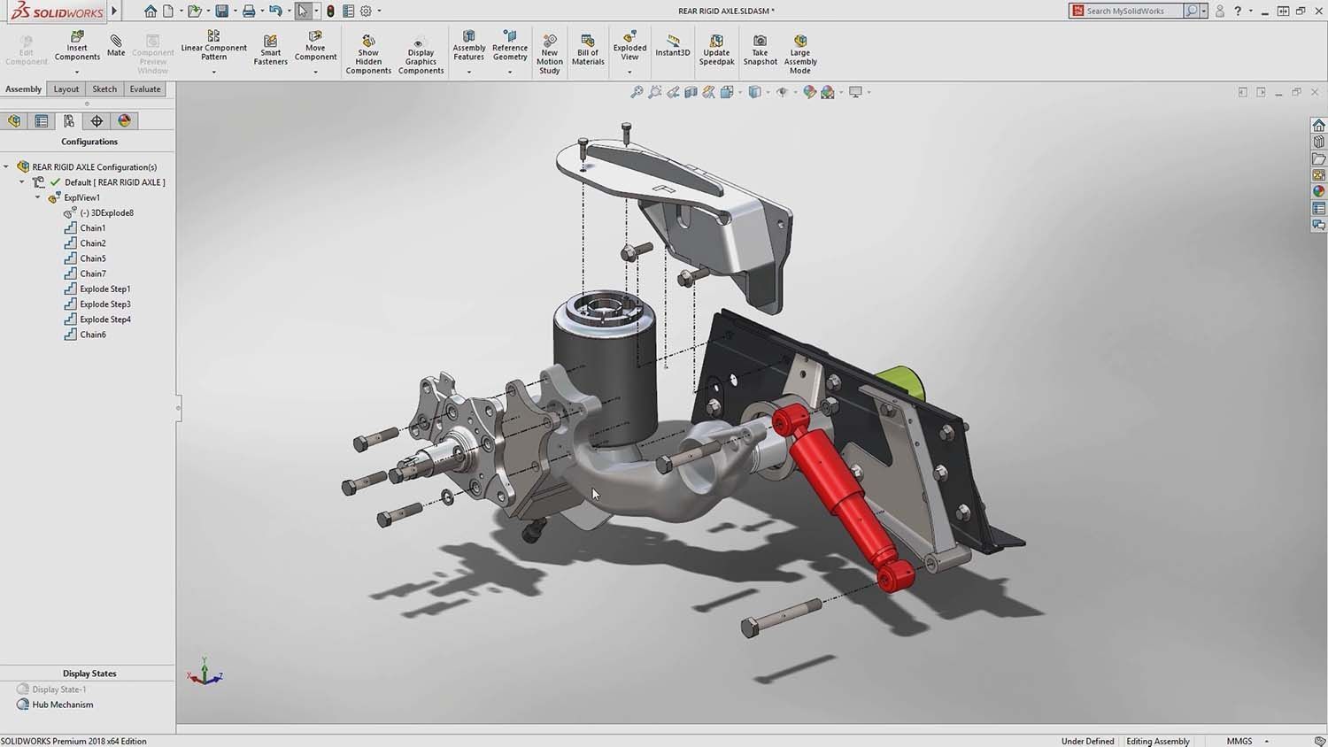
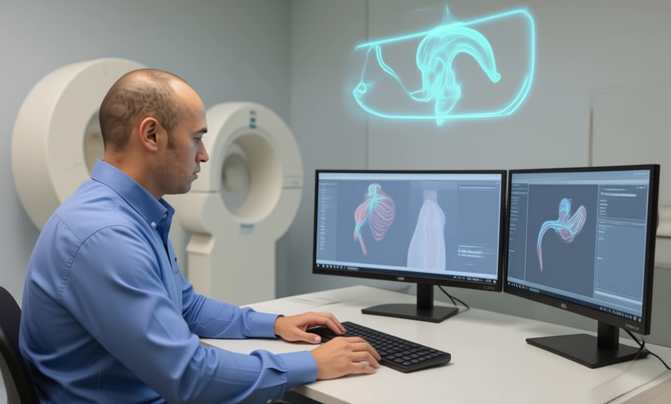
This shows, obtaining CAD data step by step from damaged three different parts to reproduce or make a new design for some recoveries, has not get any technical drawings. When these parts had been recovered, some problems occurred. These problems have been solved by referring to some practical approaches. Establishing continuity across curve and surface patches is an important concept in the free form surface modeling. The CAD models were recovered and reconstructed to consider parametric and geometric continuity. The iso-phote method was used for surface continuity analysis.
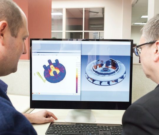
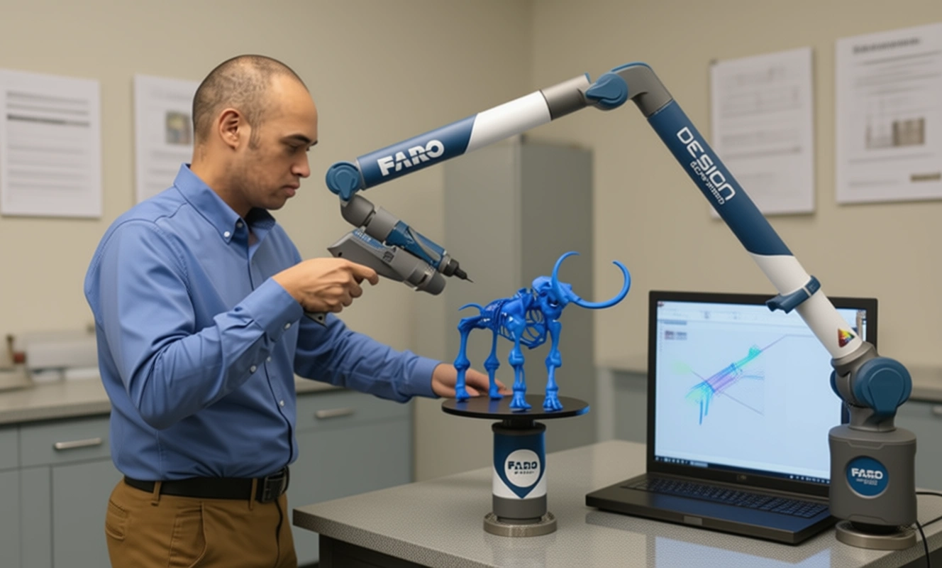
Firstly, CAD models are created from damaged and broken parts by data digitization method by using CMM and the process was explored in detailed. Later, CAD models that had been obtained earlier are transferred into CAM module of the software and G codes are taken by the NC post-processor, and finally, the parts are manufactured by means of CNC milling machine.
If you want to explore more about Reverse Engineering, other CAD software and how to master them check out our Blog Posts here or contact us here to get in touch with a Reverse Engineering expert!
There are no comments