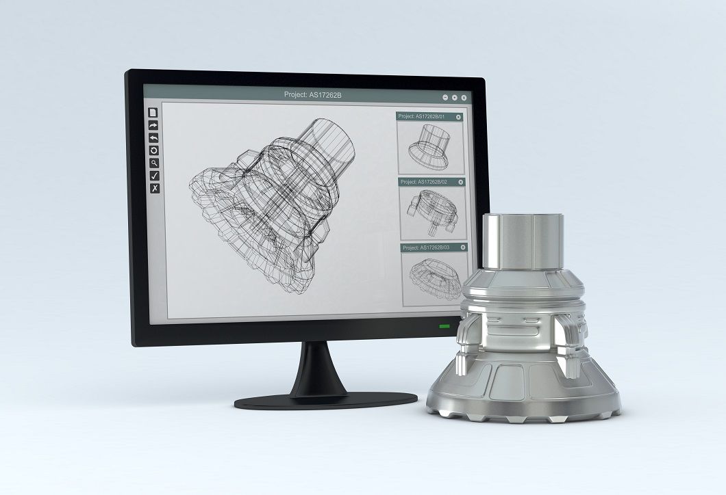
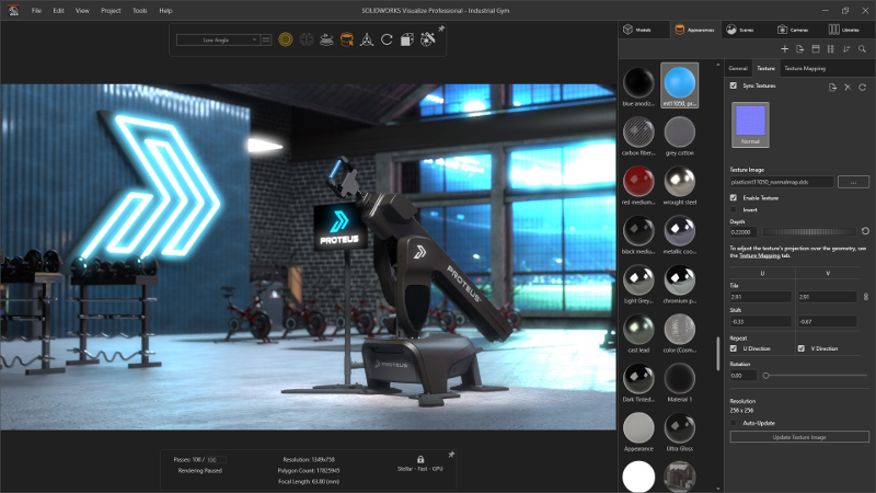
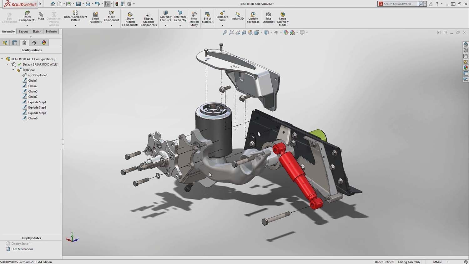
Simulations and molding Software we use:
The company Beyss from Straelen offers milled parts with Eima 5-axis CNC machining centers up to sizes of 3000 * 1750 * 900 mm.

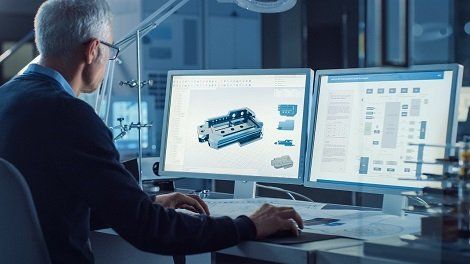
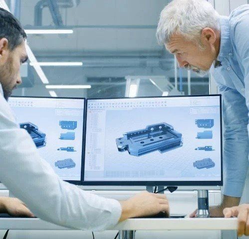
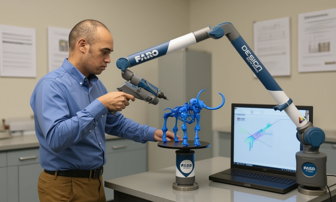
Accurate reverse engineering work done by hand
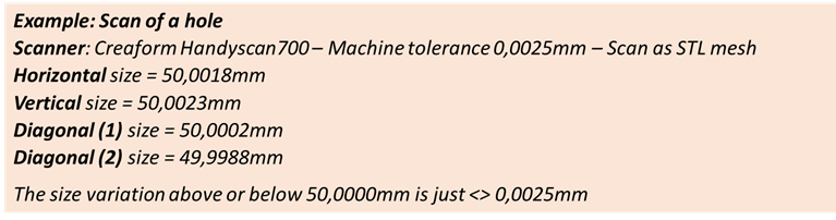
More about Tolerances:
OUR BLOG
Die besten Reverse-Engineering-Tools für Solidworks-Nutzer Für Solidworks-Nutzer, die ihre Designfähigkeiten verbessern möchten, kann die Nutzung von Reverse-Engineering-Tools Ihre 3D-Modelliererfahrung erheblich…
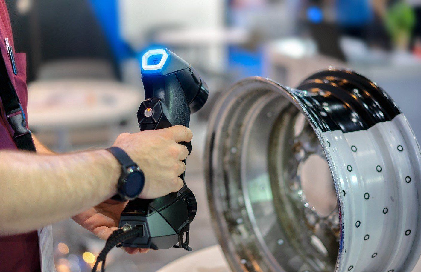
Reverse Engineering mit 3D-Scantechnologie Freischalten Die 3D-Scantechnologie revolutioniert das Feld des Reverse Engineering und bietet unvergleichliche Genauigkeit und Effizienz. Indem…
Top-Techniken für den Erfolg im 3D-Rückwärtsengineering 3D-Rückwärtsengineering revolutioniert, wie Industrien Design, Prototypenentwicklung und Produktentwicklung angehen. Durch den Einsatz fortschrittlicher 3D-Scanning-Technologie…
Die wichtigsten Vorteile von 3D-Inspektionsscannern für die Qualitätskontrolle Die Qualitätskontrolle ist ein wesentlicher Aspekt in der Herstellung und Produktentwicklung, der…